Monday 25 November 2019

Radiator, hoses, pipes, ancillaries

Steering  Pump.
If you have one from Roadcraft, the steering pump hose connection will look like this:

If it isn't obvious from the pic, I'll tell you that it is nigh on impossible to connect the hose with the pump in place. The trick is to take the short connector from the hose joint and screw this into the steering pump before the pump is fitted to the engine.

After the pump is installed, there is just enough room to get the nut on the hose joint tightened up onto the connector before installing the belt


Now the steering pump hoses can be fully connected


Starter Motor
The starter motor is mounted to the engine block. There should be approximately a 1/4" inch gap between the flywheel ring gear and the motor gear. This is so the motor gear is very much out of the way after the engine starts. It is easy to do if you have the motor to hand before fitting the bell housing. In my case I had to remove the motor from its bracket, measure the distance from the surface of the bell housing to the flywheel ring gear, and compare with the mating surface on the motor to the edge of the motor gear. The measurement was ok and Brian at Roadcraft says these things normally do not require adjusting, but the motor comes with packing spacers in case.


Radiator and hoses
The radiator fan was fitted to the upper and lower radiator mounting brackets supplied by AK.
The fan assembly comes with a few different mounting brackets which slot into the fan surround.
So drill and tap four holes in the appropriate places on the upper and lower rad mounts.

In this pic, the fan motor wires are exiting on the offside side of the fan motor.
What we learn when we get the AK wiring loom is that the wiring for the fan is bundled with the nearside leg of the wiring loom which supplies the lights on the nearside, and will in fact be within the nearside wheel arch. So if possible, fit the fan such that the wiring exits the fan housing towards the nearside. That will make it easier to connect to the wiring loom later.

The radiator mounting needs to be rubber insulated from the metal mounting brackets or else vibration is likely to crack the rad over time.
The lower mounting pins need this rubber mount:
Part no. 572312A from  Rimmer Bros.

The top mounts need a rubber washer.
I used part no. 500447 from Rimmer Bros and then cut it in half to get the correct thickness for the top mount.

In fitting the rad, make sure it fits without being twisted out of shape. I had to re-form the top AK supplied mounting bracket so it would line up with the screw holes in the rad. And also such that when the mounts are tightened down there should be no stress or twisting motion on the rad.
Note the bottom outlet pipe from the rad. It may possibly interfere with the lower mounting bracket. Cut away a small corner of the bracket if so.

The hoses supplied by AK fit well after being cut to correct length. Use a very sharp Stanley knife.
A jubilee clip can be put round the hose to guide the knife cut.
When fitting the jubilee clips think about access to the screw head after the car is built. It will be from underneath or in through the bonnet. Position them such that you will be able to access the screw head.

The top chrome pipe is secured to the chassis arm with a 38mm P-clip.
The lower chrome pipe is possibly done the same way but I didn't like the way it was holding the pipe. I wanted a strong clamp that surrounds the pipe, something like a saddle clamp. And what I found is actually called a 'Cobra Pipe Clip'. How serendipitous. I had to get me one of those.
And here it is:


Mount the header tank to the right hand side to make way for the air inlet pipe when I have the money to buy it!


Around this time, if you have an idle motor with a cable operated throttle, you may want to think about fitting it now. It comes with an Omex kit from AK. Ideally it mounts on back side of the chassis cross member under and to one side of the header tank. It has two hoses coming up off it so consider its position in relation to the header tank and the large air inlet tube.
This is it here:


One of the hoses goes to the front port on the air inlet tube.


The other hose goes to the port upstream of the throttle body that was vacated when you removed the EVAP sensor.


Exhaust Headers
If you have a crate engine in the UK, it will probably have headers that need changing to fit the AK chassis. Roadcraft can source new ones, I obtained a used pair from a Ebay dude in the States.

Had them media blasted to get the rust off. And then due to the top chassis rail on a GenIII chassis cut/grind the heat shield mounting lugs down. Then paint with very high temperature POR paint (thanks James).

The bolts securing the original headers appeared to have some form of thread lock from the factory.
I couldn't find any thread lock that will put up with the temperatures we will get here (~800c +).
Several internet forums in the States talk about not using thread lock but to use a small dab of copper grease so as to stop the metal/all corrosion happening. If we find the manifold blowing after some mileage, it may be due to the header gasket relaxing and the retaining bolts may need to be tightened.

Dipstick
This caused me a lot of problems.
As we have changed the sump, we also need a dipstick (DS) and tube which will properly measure the oil level in this sump. As I had the parts supplied from Roadcraft instead of having them pre-fitted, I had the original DS and its tube as well as the new one.
In order to get the new tube to fit, it has to be modified to bend around the now changed exhaust headers. The bracket that screws it to the engine block is now useless. I cut it off.

Originally I planned to create a new bracket with a hole and rubber grommet for the tube.
The two problems are that the rubber will probably melt, and it won't hold the tube securely, allowing it to possibly rise up out of the hole in the sump.

So I had to weld it. I have used oxy-acetylene years ago but I don't have the equipment for that at home. I only wanted to braze it anyway due to the thinness of the tube. I bought the kit to use a propane flame from the space heater but it was hopeless. It takes so long to get the heat up that oxides start forming ruining any braze joint that might have happened if I could get it hot enough.
There is a lot of Internet advice about brazing with propane, don't believe it. You will need oxygen.
The Welders Wharehouse (google it) sell a Oxy-Gasex kit. This deliveres a 3000+ degree C flame with a nice blue tip that works very well. It may be possible to weld 1mm - 2mm steel as well but probably only with autogenous welding (without use of a filler material).

When bending the tube, make gentle curve adjustments or else nothing will get down it if the bend is too acute.
Now, after bending the tube to suit, you'll probably find the DS itself will no longer fit down the tube. That is because it may be of a flat blade type. I used the original, longer, twisty DS but cut to correct length. The original one is made using twists instead of flat blade.


It means it can bend in any direction and so will slide down the tube. If you don't have the twisty type, the original flat blade can probably be warmed up and twisted to form the twist shape.


The longer twisty but now cut to length DS is below in the pic above. I drilled two tiny holes to mark the upper and lower levels the same as the flat blade DS that should be used

The bracket I made is bolted to the engine block and brazed to the DS tube. Painted with high heat POR (Thanks again James).


I have to say it is not my most elegant work, but it will do the job.


Sunday 6 October 2019

Engine and gearbox

I have probably spent quite some time figuring out the best and most cost efficient way to secure an engine and transmission setup. It is a big part of the budget so I took to investigating all options before returning to the first option.

The fact of the engine being a Chevrolet LS3 was set in stone as the chassis has the correct mounts for that engine. It does come in a variety of power outputs. The basic crate engine is quoted as 430bhp, then with different camshafts we get up to 525bhp. There are murmurs about whether a 525bhp version will pass IVA emissions test. Some folk say just dial down the mixture for the test, others says it's not that simple. With a specialist build the LS3 can be up over 575bhp. But it all comes at a cost.

Regardless of the state of tune, the main thing is how to source the engine.
I costed up obtaining parts and building it myself. it worked out more expensive than a crate engine off the shelf.
I discussed with various folk about appointing a specialist builder. One company said that unless I need a special build for racing, don't bother as the cost is not worth it. There are individuals who will build engines. I have had various good and bad reports. For the kind of money we are talking about I want to have a reasonable assurance that the supplier is going to be around in the event of problems.

Next was to look at sourcing a crate engine from a supplier in the States. Their quotes are about the same as in the UK with VAT. Add in transport and import stuff and that makes no sense. Which is a shame as these things are everywhere in the States, you'd think they would be cheap as chips. I did make contact with an engine builder in California who promised a bespoke build to my own spec way cheaper than I can get in the UK. Sadly no quote was actually forthcoming despite a couple of attempts at chasing it.

The thing is that a standard crate engine won't fit in a AK Gen III chassis. It needs a bit of work. The oil pan has to be changed to a 'F' body type. There are changes to the alternator mounting bracket and power steering pump. And the exhaust headers will be the wrong type. The correct headers are not easily available it seems.

So what to do.
The answer is phone up Brain at Roadcraft, put an order in for a LS3 430bhp and a Tremec TKO600 'box. Roadcraft know all about AK Cobra chassis and will supply everything you need for the engine to drop straight in with no worries.
There are cheaper ways of getting a power plant if you put the effort in to get an old engine and refurb it etc. But this is by far the easiest and the least hassle.

Regarding the Tremec 'box. It comes with two different 5th gear ratios. .82 and .64. The .82 is a closer ratio and you will be pulling about 700rpm more than with .64 5th gear. The .64 option is quite a big drop in revs when changing up from 4th. It is probably a proper overdrive and gets you a bit better fuel consumption and a more relaxed ride on the motorways. The potential issue is that around 60 - 65 when you want to change up, the revs may drop out of the usable torque curve and the engine gets bogged down. Especially true if engine is in a higher state of tune where the usable torque is pushed further up the rev range. I went for the .82 as I think it will be more usable under most circumstances.

What I did want though is to get the engine from Roadcraft as a crate engine and do all the work myself assembling the Serpentine belt and pulley systems at the front, swapping over the oil pan and assembling the clutch and flywheel.
It saves a few bob and is nice to get intimately acquainted with your weapon of choice for power. Roadcraft will supply everything you need boxed and ready for assembly.

Delivery:


I am very pleased to say that I happen to know a splendid chap called James who loaned me his engine hoist. Here the engine is resting on part of the original crate it arrived in while I work on it. Saved money on buying/hiring an engine stand.
Changing the oil pan means laying underneath the block. So I secured the arm of the hoist to a rafter in case the hydraulic unit failed. This also doubles up to relieve pressure on the hydraulic unit.


Before you start, remove this thing:

It is at the front near side of the engine and has a black plastic pipe connecting to a port in the air intake body.
It is a sensor called EVAP. The ECU harness will not be using it and you will need the port, that the end of the plastic tube connects to, for the idle motor when you get it from AK.
Unless you are using fly-by-wire throttle that is in which case you don't need an idle motor.


Next, change the oil pan. It is a no brainer except that when fitting the new pan, do not tighten the bolts until the bell housing has been temporarily bolted on the back. The lower part of the oil pan butts up against the bell housing and it must be aligned so the oil pan doesn't put the bell housing out of line. Also use some grey RTV gasket at the corners. The original residue shows where.

Then assemble brackets, alternator, power steering pump, pulley, tensioner and power steering pump reservoir.

 The pump and pulley mount on the alternator bracket. There is smaller bracket that provides rigidity to the pump. There are three bolts securing it through the pump wheel here:


 There is a small black bracket for the pump reservoir that fits to two of the alternator bracket bolts. I removed the label after the photo!

There is a small tube that connects the pump reservoir to the pump.
The outlet to the steering rack is at the bottom of the pump. Keep it blocked off until ready to install the line.

And here it is. The tensioner is on the far left. Use a socket and bar on the central nut to move the tensioner in to get enough slack to slip the belt on.


Torque settings are:
10mm bolts: 38lb/ft
8mm bolts: 18 lb/ft
8mm oil pan bolts: 18 lb/ft
6mm long oil pan bolts: 9 lb/ft.

At the rear we find the clutch and bell housing.
Remove the flywheel if it is fitted.
Clean all bell housing and crankshaft surfaces.
Install the bell housing with all retaining bolts tightened to spec.
Install the magnetic mount for the dial gauge  through the housing and mount securely on the end of the crankshaft. It doesn't have to be central, it can be offset from the crank centre line, but it MUST be flush with the crank surface.
Set the dial gauge so it is going to read on the inner surface of the opening to the bell housing.


Remove the spark plugs so we can turn the engine over more easily.
At the front, looking at the front, the crankshaft rotation is clockwise when running. That is to say a socket on the central pulley will be in the 'tightening' up direction. I put a crack bar on it so I can move the crank round.
Set the dial gauge to zero at 12 o'clock. Turn the crank to take readings at 9, 6 and 3 o'clock. Return to 12 o'clock and check the gauge is back at zero to check it has not moved.


The maximum offset is 5 thou.
My readings were:
12 o'clock = 0.00mm
9 o'clock = +0.03mm (1 thou)
6 o'clock = +0.01mm (0.4 thou)
3 o'clock = -0.05mm (2 thou)
This was checked 5 times with the dial gauge reseated twice.
It seems the block and housing are quite well engineered.
If you have more than 5 thou variance you may need offset dowel pins, or you have a dodgy crank or block or dial gauge, or all three.

Installing the flywheel.

The threaded holes for the flywheel bolts are drilled all the way through to the engine internal.
So there is a risk of oil under pressure seeping past the bolts into the clutch area. Use a reasonable amount of blue loctite or else grey RTV gasket stuff.
Have a small amount of grease under the bolt heads so as to relieve friction when torquing them up.
The bolts are tightened in at least three passes. And torque them in crossed order.
1st pass 15 lb/ft
2nd pass 37 lb/ft
3rd pass 74 lb/ft
Install the crank centre bearing with the lip/flange to the outside. It is an interference fit and needs to be drifted in with a 34mm socket or similar. Make sure it is correctly seated.

Next comes the clutch friction plate held in place by a 36 spline, 1 1/8 dia clutch plate tool.
Finally install the clutch pressure plate. Heavy bugger it is too.
Take many passes to tighten the bolts (blue loctite) as we are now compressing the clutch release springs.
1st pass = 11 lb/ft
2nd pass = 26 lb/ft
3rd pass = 41 lb/ft
final pass = 52 lb/ft


The clutch release arm pivots on a bolt with a ball shaped head. The bolt must not protrude through the housing to the gearbox side when tightened. I needed three washers to set the bolt at the correct height. Check that the rear of the clutch arm does not foul on the clutch pressure plate when it is installed. Measure the depth from the housing surface to the back of the clutch arm and compare that with the depth from the engine surface the housing mates to and the clutch pressure plate. I found 100mm gave me ~4mm clearance to the small radial springs in the pressure plate. Blue loctite and torque to 40 lb/ft.

Take note about how the release bearing sits in the fork. The spring tabs must be inside the outer flange of the bearing.


If you have the starter motor, now is a good time to attach it and check the clearance between the starter gear and the ring gear on the flywheel. There should be .040 - .100 thou gap. Check this before installing the bell housing.

On with the bell housing.
Housing bolts = 37 lb/ft torque

Grease the far end of the gearbox shaft that goes into the spigot bearing in the crankshaft.
Line the box up and gently rock it to match the splines with the clutch plate. Operate the clutch release arm to make sure the bearing is free and not jamming on the shaft.
When the hub of the gearbox is about to go into the housing, the shaft will be engaged in the spigot bearing. Install the four bolts and gently pull the box into the housing. Make sure to keep the box exactly square to the housing as it goes in.


I cannot finally tighten these bolts up as the two on the left are also used to mount the clutch slave cylinder bracket which I don't yet have.
Put a block under the rear of the box to take the weight off its feet.


Final thing is to remove the exhaust headers and see if we can flog them on ebay.
I don't have the correct headers yet but AK assure me they will go on after the engine is installed in the chassis.

Installation in Chassis
Two essential items: A hoist, and a chap called Dale:

You'll need the hoist with an attachment that can alter the angle of the engine as it slides in.
And you'll need Dale to help sight the engine going in, to provide some wisdom about fitting engines and to help with tea drinking and cake eating. You can probably make do with a chap who is not called Dale, but I can't guarantee the same results. Anyway, thanks Dale

I  jacked the rear of the car as high as I could get it. Mainly so I can get underneath to drill and fix the bolts that secure the gearbox bracket. But it also helps with the angle the engine needs to be relative to the chassis.
Cover nearby chassis tubes to protect against knocks from the engine. I used some water pipe insulators. Remove exhaust headers if they are fitted. The starter motor and clutch slave can go on later.


At one point we had to remove the chains that were connected to the rear of the cylinder head and replace with rope down to the gearbox and a jack under the gearbox. Leaving them in place means there would have been no room to remove the bolts that secured the chain brackets as they line up with one of the chassis tubes.

The chassis rails which the gearbox mount bolts to is 3.2mm thick. I used four 10mm bolts straight into the chassis, I don't think rivnuts would provide very much more, and will need 13mm holes drilled. You can drill right through and weld studs from the top (make sure it is finished flush as I think the body needs to sit here). But wisdom from AK suggests the four 10mm bolts are sufficient.

Propshaft
Before fitting this, you may want to check the section on fitting the speedo sensor:
18 Speedo Sensor

From Bailey Morris as per everyone else.
There is a long spigot protruding from the diff flange which the propshaft flange has to slide over.
In order to get the maximum length of slip yoke onto the splines in the gearbox shaft I cut the spigot length down. The issue is that whatever length the spigot is, that is the amount which the slip yoke is not engaged in the gearbox. I'm not sure of the length of the splines in the 'box but I only have a couple of centimetres protruding so there is lots of engagement.


The slip yoke is from Roadcraft. I had to send it to Baileys so they can use it to assemble the shaft.
Baileys also supply these so next time check their prices, saves a bit of faffing with parcels back and forth.

If you have a TKO600 'box, you may have a large donut of rubber sticking out the back.
This has to be removed. Details on various websites make mention of a smaller rubber ring that can be left in place and pushed into the 'box when inserting the slip yoke.
I had this:


And it was a right bugger to get out. Use two pliers, grip hard and pull like mad.
Don't insert anything up it to try to free it. The gearbox seal is behind it and you don't dare damage that. It is really hard to pull out, but out it must come.


The retaining bolts may not easily insert into the shaft flange. I used hex bolts but still needed to shave some metal. There are three points of interference, the entry and exit of the flange holes and a corner of the UJ joint on the shaft. Grind a tiny amount from each location until the bolt slips through. The bolts need to be inserted before the shaft is fitted so the angle of the UJ joint can be used to best effect for inserting the bolts.


The measurements for Bailey Morris are the number of holes in the diff flange (three or four) and the distance from this flange to where you want the slip yoke to be in the gearbox.


So in this case it is the distance from the face of the diff flange to the center line of the UJ joint holes in the slip yoke.


When all done there is no room to get a torque wrench on them so lean on a spanner until your face goes Ferrari Red.


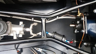
This pic also shows the relative position of the fuel pump to the shaft which is fine with good clearance.


Tuesday 24 September 2019

Fuel Tank, Lines and Filler Cap

The rear subframe the fuel tank is bolted to is 2mm steel on a GEN III chassis.
The thread pitch on a 8mm metric fine bolt is 1.25mm. I'll leave you to dwell on that while I demonstrate how I attached the tank.

One could use a stainless steel bar the full length of each side and then secure it with as many rivnuts as you feel comfortable with. I took a lesson from Stuart Holden's excellent blog and used small plates over each tank tab with 6mm bolts into rivnuts.

The tank is raised into place using a jack and then held with four small G-clamps while I drill the holes and insert rivnuts.


Later when I fit the body I'll run some sealant around these brackets to stop water and dirt ingress and paint them black.


Fuel lines.
Decide what connectors you want to use before ordering your fuel pipes. If you use AN connectors get the fuel pipe to go with them. I have used push on hose connectors from Viper Performance. They also have an excellent page on their website that explains AN fittings and sizes.

For the fuel line clips, don't use Jubilee clips. They distort and can damage the line.
Here we are using Mikalor Supra Hose Clamps from Westfield Fastners.

Lastly the fuel line ends are finished off with some little black socks purely for aesthetic reasons.


The fuel pump is Walbro GSL392 an is fitted as close to the tank and as out of the way of the prop shaft as possible. It seems these pumps do not like a filter in front of them so flush and drain the tank before connecting up.
Before fitting the pump in this location, you may consider fitting the speedo sensor here as well:
18 Speed Sensor


The fuel pump bracket is a device from Motamec. The mounting holes are inline with the bracket so it fits nicely along the chassis rail. There are two 45 degree connectors to make the fuel line as straight as possible. I am told to not use 90 degree connectors, probably creates too much turbulence and friction in the fuel flow.

In fitting the mount and lines, consider the access to the clips etc will, in future when build is complete, be from below. So do things up with respect to being able to access them from below in future.

The line from the pump is secured above the lowest point of the diff hanger with a P-clip and a 5mm hex screw.


And finally the fuel line from pump to filter.


The filter comes with two large clips for mounting. They are designed to be screwed to a flat surface. I changed them for similar clips with a single hole for a mounting screw which means the clip keeps its shape when mounted on a curved surface.

Fuel Gauge Sender
The unit supplied from AK is a TB9011/KIT from Caerbont Automotive.
The arm which moves with fuel level needs a lot of trimming down. There is a table in the accompanying leaflet from which you could derive the correct arm length using some extrapolation as the depth of the AK tank (180mm) is outside the scope of the table.
Anyway, we want to measure it ourselves do we not?

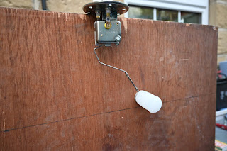
So, rig the sender unit up on a board with a single screw holding it at the top of the board.
Draw a line 180mm (7" in old money) parallel with the board edge.
I fixed mine so the float is about 20mm from the line. That leaves a small amount of fuel when reading empty.
But also check the full level. Make sure the float is close to the top of the board - which will be the top of the fuel tank. If it is too low, the gauge will read full before the tank is.
So, this is how it's done:

Note the float will submerge by about a quarter of its diameter in water so take that into account when fixing the lowest level.
And yes I know petrol has a different Specific Gravity to water. If you want to take that into account, you need a holiday.
Solder the two arms together with the supplied clips. Run solder the length of the joint between the two arms.

Lay some grey RTV gasket or similar each side of the round cork gasket and secure with six screws. They are not equidistant so the holes only line up in one position.
But, do not put loads of gasket stuff on so that it oozes out, and absolutely DO NOT get it into the screw holes. What will happen is that you put the screws in, the RTV gets pushed in and drops into the bottom of the tank. When you run low on fuel it will get sucked into the fuel pump so blocking the flow. When you phone Jon up to ask him if he agrees with you your diagnoses that the fuel pump is bust, he'll tell you what has probably happened and call you a plonker. And let's face it, he'll be right.

Fuel Filler Cap
Later, when the body is fitted, we'll be wanting some way to be able to fill 'er up at the local gasoline emporium.
So, fuel filler cap and flange from Brasscraft. Where else?
The option is to glue it on or drill and bolt it down. If we screw it down we'll need some counter sunk screws. So drill out the holes in the flange to 5.5mm then use a proper countersink tool to grind out to a depth were the screws will sit slightly below the surface. If any sit even just slightly proud, the cap will not screw down into position properly. This is a bit important as when you set the location of the flange, it will dictate the final position when the cap is screwed down. And the cap has to be in a certain position to pass IVA - so I hear.


As we are screwing the cap down after the flange is bolted down, it has to have clearance around the the raised bodywork as it is turned. To facilitate as such, the flange has to be offset to the central position of the cutout. In my case it was 8mm rearwards of the centre position.


And here is the cap screwed down into place in what I understand to be the IVA acceptable position.


Next we need to connect the cap to the fuel tank. CBS sell a super flexible hose, 51mm ID and in 500mm lengths. Sadly you will need around 530mm - 560mm so order two which will come in a 1000mm single length.

The hole in the wall of the boot need not be too large if the hose does not pass through at a too acute angle.

The dimensions I have is: 63mm x 78mm and located 111mm fup from the floor of the boot.


And then lined with the off-cut of the rubber trim AK supply for the bonnet.

The hole for the breather pipe is separate and is lined with a rubber grommet.


There is now but a small gap around the filler hose that will be filled with black rubberised sealant.


Breather Pipe
Discuss.
As fuel is used, air needs to replace it or we get a partial vacuum.
With changes in ambient temperature, fuel can expand so air needs to get out or we get positive pressure. So we have a breather pipe, but what to do with it.
One can purchase an inline breather/vent valve. This device will allow the fuel tank to 'breath' and some of them have a device to stop fuel leaking out in the event of the car being upside down. Newton and Mocal make them and you can get them from Merlin, Demon Tweeks etc.
But that isn't quite what AK do. The solution here is to connect the breather pipe into a 'T' piece in the main fuel inlet pipe (AK will flog you one). The 'breathing' then takes place through the fuel cap which actually isn't air tight.
Four small holes are also drilled into the small internal locking fuel cap to aid this air flow.
You may wish to consider that as we now have a closed loop between the breather pipe and the main inlet pipe that the breather pipe is now a bit redundant. It is, apart from the fact it also helps to get air out of the way when filling the tank and helps to stop back pressure when the fuel is going in.
I have set mine up accordingly, so we'll see.