By now we should have a fully functioning car, but without any seats or much of a cockpit to speak of.
Sadly, a lot of it now has to be stripped off so it can get a coat of paint, assuming you don't have a gel coat base colour.
You can of course have anyone paint it but the chaps who hang out next door to AK know exactly how it's done and their work seems to be as good as it gets. Plus we can have AK look over the build and laugh/admire your work and suggest changes you may need to make, especially for the IVA test.
So, remove all lights, bars, windscreen, fuel filler, exhaust silencers, wash and wipers.
Remove the chrome cover on the door lock but leave the lock in place. Leave the rubber door trim in place. Leave the boot and bonnet rubbers in place. Leave off the inner cockpit panels. Remove the handbrake and tie the cable out of the way if you have the large Jag wheels fitted from the donor car.
The boot and bonnet gas struts must be fitted as well as the boot handle and the bonnet handles.
The work on the car will include improving the fit of doors, bonnet and boot and of course repairing, fixing up all blemishes etc on the body.
The inner skins of the boot lid and bonnet will be painted body colour if you wish.
As the above items are removed, check the clearance around the fitments. The paint will take up a millimetre or more so make sure everything has a reasonable clearance for when you refit.
Same with the dashboard. Make the holes for switches, instruments and lights up to 2mm larger to allow for the leather covering which will be folded into the holes, but maybe only 1mm for the small lights which are just a push fit.
At the same time, drop of the doors cards with the dashboard for the trimmer unless of course you have your own solution. Spend absolutely hours with Wendi choosing colours and the finish of the cockpit. Drink several cups of coffee, a few biscuits and when done make your way home to an empty garage/workshop and wonder what you are going to do for the next four weeks or more. In my case, decorate the kitchen.
Sunday 12 July 2020
Nudge Bars
I purchased the nudge bars from Europa Spares, complete with over riders.
They are IVA compliant, so I am reliably informed, and seem to be very good quality.
The rears are easy to fit. There are support brackets in place inside the boot and under the rear chassis rail. The rear bars from Europa come with tubes that fit through the body so we don't need separate chrome tubes here.
 The holes are marked on the body, but check for exact location to get the bar central and level.
Drill out the holes and go all the way through into the support brackets. Using some 10mm threaded tube, locate the bars into place. You may need some washers against the brackets to even up the bar if there is a difference in exact location of the brackets that are bonded into the body.
Here I have temporarily fitted with nuts in place of the over riders to get the positioning correct.
The front bars are more difficult. We will need to source some chrome tubing to cover over the 10mm threaded bars. AK will supply two right angle brackets to fit inside the inner wing.
 First assemble the over riders onto the bar, then insert just the top two threaded bars into the upper holes of each over rider. Offer up to the body and when happy with it being central and level, drill the holes to 8mm. I started with 3mm drill perpendicular to the body surface, then a 6mm drill at an angle finally a 8mm drill angled in line with how the threaded bar will enter the body. Then open up with a round file until we are about 2mm larger than the threaded bar. Now we will have the exact position for the two lower holes once we have the bar in place and located in the upper holes.
Fit the AK supplied bracket to the inner front wing and mark where the four threaded bars will meet with it. Here drill oversized holes as we'll need some variance to move around in whilst getting the bars dead central in the body work holes. Note that when tightening the brackets to the inner wing, they may distort and want to pull the threaded bars out of position so make sure everything is square.

Here we see the lower bar is set to low in the bodywork hole after mounting with the bracket.
That is ok as the hole needs to open up more to accept the chrome tube that will cover the threaded bar. So in that case I just open up the hole in one direction until the bar is central again and I have enough clearance for the chrome tube.

To save the wear and tear on the chrome tube, I used aluminium tubes of the same size to test fit and eek out the holes to the correct size.
I think next time I'll just go with over riders and lose the bars.
Monday 6 July 2020
Bonnet and Boot lid
Or Hood and Trunk if you are from across the pond.
Boot lid
We probably need to file away some parts of the lip edge around the boot where the rubber sits in order to get the lid to sit flush with the body. So fit the rubber trim and mark where it needs to be relieved to get the lid to sit flush. I had to cut a fair amount away from the rear section. Be aware that where the lid protrudes it may not be right under there that the edge needs trimming. The lid can be held proud by an edge that needs filing down some inches away.
The boot lock, handle and hinges are from SandJ.
The hinges are slightly different left and right. Fit them so the upper surface of the hinge is horizontal. The surface they sit on falls away with the curve of the boot lid. Fit them nine inches either side of the centre line you have managed to work out and draw down the centre of the car.
 You'll be wanting to fit the handle dead centre of the boot lid. So work out just what is dead centre and drill the hole. Open up to suit the boss at the back of the handle and make the small cutouts for the locating lugs. I bonded two nuts with washers on the inside of the lid so I didn't have to use self tap screws which may not be very robust.
There may also be a possibility to drill and tap two holes into the lock mechanism so you can insert screws all the way through and screw into solid metal but I would need to take the thing apart to check if that is viable and I'm not doing that now it is all in place. The AK preference is to cut the small lugs off and drill for self tap screws. Apparently if the bonded nuts come loose when the handle is removed for painting it causes a fair amount of angst when putting it back again.
Boot lid
We probably need to file away some parts of the lip edge around the boot where the rubber sits in order to get the lid to sit flush with the body. So fit the rubber trim and mark where it needs to be relieved to get the lid to sit flush. I had to cut a fair amount away from the rear section. Be aware that where the lid protrudes it may not be right under there that the edge needs trimming. The lid can be held proud by an edge that needs filing down some inches away.
The boot lock, handle and hinges are from SandJ.
The hinges are slightly different left and right. Fit them so the upper surface of the hinge is horizontal. The surface they sit on falls away with the curve of the boot lid. Fit them nine inches either side of the centre line you have managed to work out and draw down the centre of the car.
 You'll be wanting to fit the handle dead centre of the boot lid. So work out just what is dead centre and drill the hole. Open up to suit the boss at the back of the handle and make the small cutouts for the locating lugs. I bonded two nuts with washers on the inside of the lid so I didn't have to use self tap screws which may not be very robust.
However if you do want to use self tap screws, you will need to grind or cut the small locating lugs off. Now you only need to drill the round hole for the handle, as close as possible so as to leave enough meat in the fibreglass to take a couple of self tap screws to hold the handle on.
There may also be a possibility to drill and tap two holes into the lock mechanism so you can insert screws all the way through and screw into solid metal but I would need to take the thing apart to check if that is viable and I'm not doing that now it is all in place. The AK preference is to cut the small lugs off and drill for self tap screws. Apparently if the bonded nuts come loose when the handle is removed for painting it causes a fair amount of angst when putting it back again.
Behind where the lock sits there is a box section built into the lid. In here we will fit the lock mechanism.
The position is dictated by the position of the square peg from the handle. Looking at the lock mechanism the square hole for the peg is offset, so it is a bit awkward to fit the bracket. It just about fits, the box could do with being slightly wider.
 To make the fitting easier, I welded two nuts to the lock mechanism so I didn't have to cut the hole in the box so large as to fumble with loose nuts inside. When I do this again I'll weld the nuts to the other side of the plate which would make more sense.
 If you cut the square peg to size before fitting, you won't need to drill right through the box section. After cutting down the square peg I filled in the hole ready for painting.
 The catch that the arm locks into is mounted back up against the rear edge. In fact I had to cut a small section away to get it to sit back enough for the arm to properly engage.
Gas struts
I went a bit off message here. AK can supply gas struts and all the brackets to fit the bonnet and boot.
There are two reasons I went my own way on this and one of them is about doing stuff myself if I can. And as it turns out, I could. So I did. So there.
From SGS Engineering:
Two gas struts GSV6-150
Four 10mm metal ball stud T4
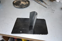
We need some brackets. For the bottom brackets I made a wire template to get the shape of the bracket which fits under the rim of the rain channel.
The resulting bracket looks a lot like this.
 Two holes drilled for the screws that will attach through the rain gutter, and one 8mm hole for the lower ball joint.


Fix in place by bonding with P38 and two screws. I was going to pop rivet but the nose of my new expensive rivet gun was too wide to get into the rain channel.
The brackets are made from 1.6mm thick stainless polished to give a brushed metal look. For positioning follow the guidelines from Jon's video in the member's area on the AK web site. So from the front edge of the boot, measure longitudinally back 16 and a half inches and mark this across on the left and right edges of the boot. Line up the middle of the bracket and fix in place with the P38 and rivets/screws.
For the top bracket I tried a number of solutions and ended up with this:
 The bracket is in two pieces which are welded together. An 8mm hole is drilled for the 10mm ball joint and two small holes for self tap screws to go into the rib on the underside of the boot lid. I was going to bind this as well with P38 but the fit was so solid I left it with just the two screws. Not sure if the spray shop will want to remove them when they spray the inside of the lid.

Mark on the body the centre line of the bottom bracket. Shut the lid and measure 10 inches back and mark the lid. Open the lid and fit the bracket so the centre line of the bracket is on the mark. If you have made the bracket correctly it should be a tight fit on the rib of the lid. Secure with two self tap screws and fit the strut
As before, the bracket is polished to a brushed metal look.
 The gas rams need some gas bleeding out, quite a lot actually but do it equally on both struts and open the grub screw for a second at a time. It needs quite a push to get the strut to move so don't let too much out. Fit the struts and then fine tune it by letting gas out half a second at a time until the lid will close with a push. When the lid opens, you may find one strut reaches full extension before the other. So you may need to slightly adjust the position of one of them so they both reach full extension together.
If you do go too soft, return the strut to SGS and they will refill for around half the price of a new one.
Bonnet
I've gone a bit alternative with this. Gas rams on a bonnet? How very ostentatious.
As with the boot lid we need to fit the rubber surround and work out where to relieve the edge so the bonnet fits flush all round. I did this with the bonnet attached to the hinge that comes with the body so I could understand the final placement of the bonnet. Take notice of the front edge of the bonnet as you open and close. It may come close to or actually interfere with the body. The hinge is adjustable for location and it is obvious to move it rearward to increase the front gap if necessary. But there is more to it. The hinge can also be made to vary its location vertically, the holes it locates in are quite large and allow for a fair bit of movement. Moving the hinge vertically alters the profile of curve the bonnet will describe as it opens. So moving it up will increase the amount of vertical movement before it starts to move forward on its journey around the curve. This will help it clear the body in the first few inches of opening.
Bonnet locks. First decide what lock cams you want to use. There are two types. One long, the other short.

The short one means you will need to fit a bracket that extends a little way into the engine bay as the lock has to be set in a certain position through the rib in the bonnet. That being so, the short cam isn't long enough to reach under the rain gully.
 I used the long version. But if you do, note that there is a possibility that if the bonnet happens to be shut with the locks in the 'engaged' position, they could mark the paintwork on the body.
To avoid that I found I could position the handles far enough back so the cams just close down inside the body, but still protrude far enough to locate themselves under the rain gully.
So. mark and drill the holes for the handles, open up and cut the small cutouts for the locating pegs.
Be careful to get the square peg appearing through the ribbed section under the bonnet so you have room enough to set the fixing screws with nuts.
 On one side the hole for the screw was on the edge of the curved rib so I had to shape the nut to fit the curve and then tighten the screw from above while holding the nut in place. But the finish looks ok.
Fit the locking cams and trim the square peg to size.
The position is dictated by the position of the square peg from the handle. Looking at the lock mechanism the square hole for the peg is offset, so it is a bit awkward to fit the bracket. It just about fits, the box could do with being slightly wider.
 To make the fitting easier, I welded two nuts to the lock mechanism so I didn't have to cut the hole in the box so large as to fumble with loose nuts inside. When I do this again I'll weld the nuts to the other side of the plate which would make more sense.

Gas struts
I went a bit off message here. AK can supply gas struts and all the brackets to fit the bonnet and boot.
There are two reasons I went my own way on this and one of them is about doing stuff myself if I can. And as it turns out, I could. So I did. So there.
From SGS Engineering:
Two gas struts GSV6-150
Four 10mm metal ball stud T4
We need some brackets. For the bottom brackets I made a wire template to get the shape of the bracket which fits under the rim of the rain channel.
The resulting bracket looks a lot like this.
 Two holes drilled for the screws that will attach through the rain gutter, and one 8mm hole for the lower ball joint.

Fix in place by bonding with P38 and two screws. I was going to pop rivet but the nose of my new expensive rivet gun was too wide to get into the rain channel.
The brackets are made from 1.6mm thick stainless polished to give a brushed metal look. For positioning follow the guidelines from Jon's video in the member's area on the AK web site. So from the front edge of the boot, measure longitudinally back 16 and a half inches and mark this across on the left and right edges of the boot. Line up the middle of the bracket and fix in place with the P38 and rivets/screws.
For the top bracket I tried a number of solutions and ended up with this:
 The bracket is in two pieces which are welded together. An 8mm hole is drilled for the 10mm ball joint and two small holes for self tap screws to go into the rib on the underside of the boot lid. I was going to bind this as well with P38 but the fit was so solid I left it with just the two screws. Not sure if the spray shop will want to remove them when they spray the inside of the lid.
Mark on the body the centre line of the bottom bracket. Shut the lid and measure 10 inches back and mark the lid. Open the lid and fit the bracket so the centre line of the bracket is on the mark. If you have made the bracket correctly it should be a tight fit on the rib of the lid. Secure with two self tap screws and fit the strut
As before, the bracket is polished to a brushed metal look.
 The gas rams need some gas bleeding out, quite a lot actually but do it equally on both struts and open the grub screw for a second at a time. It needs quite a push to get the strut to move so don't let too much out. Fit the struts and then fine tune it by letting gas out half a second at a time until the lid will close with a push. When the lid opens, you may find one strut reaches full extension before the other. So you may need to slightly adjust the position of one of them so they both reach full extension together.
If you do go too soft, return the strut to SGS and they will refill for around half the price of a new one.
Bonnet
I've gone a bit alternative with this. Gas rams on a bonnet? How very ostentatious.
As with the boot lid we need to fit the rubber surround and work out where to relieve the edge so the bonnet fits flush all round. I did this with the bonnet attached to the hinge that comes with the body so I could understand the final placement of the bonnet. Take notice of the front edge of the bonnet as you open and close. It may come close to or actually interfere with the body. The hinge is adjustable for location and it is obvious to move it rearward to increase the front gap if necessary. But there is more to it. The hinge can also be made to vary its location vertically, the holes it locates in are quite large and allow for a fair bit of movement. Moving the hinge vertically alters the profile of curve the bonnet will describe as it opens. So moving it up will increase the amount of vertical movement before it starts to move forward on its journey around the curve. This will help it clear the body in the first few inches of opening.
Bonnet locks. First decide what lock cams you want to use. There are two types. One long, the other short.

The short one means you will need to fit a bracket that extends a little way into the engine bay as the lock has to be set in a certain position through the rib in the bonnet. That being so, the short cam isn't long enough to reach under the rain gully.
 I used the long version. But if you do, note that there is a possibility that if the bonnet happens to be shut with the locks in the 'engaged' position, they could mark the paintwork on the body.
To avoid that I found I could position the handles far enough back so the cams just close down inside the body, but still protrude far enough to locate themselves under the rain gully.
So. mark and drill the holes for the handles, open up and cut the small cutouts for the locating pegs.
Be careful to get the square peg appearing through the ribbed section under the bonnet so you have room enough to set the fixing screws with nuts.
 On one side the hole for the screw was on the edge of the curved rib so I had to shape the nut to fit the curve and then tighten the screw from above while holding the nut in place. But the finish looks ok.
Fit the locking cams and trim the square peg to size.
You need to know however that as with the boot lock, the AK preference is to use self tap screws into the surface of the bonnet having cut the small locating lugs away so as to leave enough area to drill a small hole to fit the self tap screws. Again, you need to decide how robust that is going to be. The issue with drilling through to the inner rib, as I have, is that if you tighten the nuts too much, the upper surface of the bonnet will be pulled in and will distort. To counter that one can fit small spacers between the inner rib and the underside of the surface so as to provide support when tightening the nut.
 Since the cams now reach quite happily under the rain gully we don't need big brackets extending out into the bay area. But we can't leave the cams to constantly rub on the fibre glass as they open and close so make up some curved stainless steel covers and bond them into place with plenty of P38

Finish off by painting them engine bay colour. Black in my case.
And here's how it looks

Gas struts
Well, there aren't any.
If you do fit them know that they will tend to push the bonnet out of place when shut, so you need to have them fitted when figuring out the fit of the bonnet. You also need them installed when the car goes to the paint shop.
I have a different solution to raising the bonnet and ensuring it stays up when it is raised. I was going to write it up but as I have not seen the same solution anywhere else I thought I would keep it as my own little USP.
 Since the cams now reach quite happily under the rain gully we don't need big brackets extending out into the bay area. But we can't leave the cams to constantly rub on the fibre glass as they open and close so make up some curved stainless steel covers and bond them into place with plenty of P38
Finish off by painting them engine bay colour. Black in my case.
And here's how it looks

Gas struts
Well, there aren't any.
If you do fit them know that they will tend to push the bonnet out of place when shut, so you need to have them fitted when figuring out the fit of the bonnet. You also need them installed when the car goes to the paint shop.
I have a different solution to raising the bonnet and ensuring it stays up when it is raised. I was going to write it up but as I have not seen the same solution anywhere else I thought I would keep it as my own little USP.
Wednesday 1 July 2020
Doors and Surrounds
Then fit the door lock using four 8mm nuts as spacers in place of the covered door card.
Make sure the door sits correctly when pressed shut against the door trim. Feel the edges are flush to the body and the door level is correct at the top rear where it meets the bodywork.
 After removing the chrome cover, the four screw holes need to be opened up and on one of them the edge of the casting needs to be relieved to allow the countersunk screw (which AK supply and are screwed in place into the door when the body is delivered) to properly sit in place. Tape the lock handle in case it gets marked.
 Tape the door shut so it is tight against the rubber trim.
Assemble the catch into the curved backing plate and locate the catch solidly into the door lock.
A short length of tube or collar is required to fill the gap between the catch and the backing plate.
Allow a small gap between the curved backing plate and the door frame so we can get some P38 in there. Now screw the domed nut on finger tight. You should now see the final position of catch and plate.
Next. some woodworking. The catch plate needs some support or it will shift when your Significant Other gets out of the car after arguing about directions and she/he slams the door shut. To prevent that, either just agree with everything he/she says or cut/carve two pieces of wood which will jam into place between the curved backing plate and the bodywork. Don't carve it exactly as you want some space for P38 filling. So slather lots of it onto the curved plate, and all around the wooden blocks. When it is all in place and before it sets tighten up the domed nut behind the curved plate. Leave at least overnight as the P38 filling will be quite deep and needs a while to properly set. When done rub down the rough bits for finishing. The carpet will later fit over all this so make sure you have a bit of clearance or the carpet will be sticking out above the level of the door trim.


The other wooden blocks are to provide support to the panels AK flogged you with the body. You need to assess how thick they need to be in order to have the panels sit below the door trim, not up with it or along side. These will have a carpet covering and you don't want the edge of the carpet proud of the door trim. I have found that the door hinges interfere with this panel when it is placed against the scuttle uprights. It may be that some offsets are needed to bring the panel out a little away from the hinges. Also consider that the windscreen brackets will be down here. I cut some holes in the panel where the bolts holding the windscreen brackets are. The panel can screw into the wooden blocks and either tie wrap or self tap screws into the scuttle uprights.
The drivers side is the same story apart from carving the wooden blocks out to account for the battery cable and wiring loom.

Door Cards
More woodworking. The manual says 3mm ply but 3.6mm is more easily available and will do the job.
Don't just cut it equally 5mm in all around the edge of the door, it isn't an equal fit all round.
Shut the door and run a felt tip pen round the edge of the trim. That will be the line you need to cut the plywood to. It needs to be just off the edge of the trim but with no significant gap. When it is covered you want the door card to just press into the rubber trim so it seals.

Also leave a small gap at the top where it butts up against the moulding of the door.
Test fit the card to make sure it follows the line of the rubber trim and then sand a chamfer along the edge to give room for the covering when the door shuts.Drill holes for the lock mechanism and ten holes about 15mm in from the edge for the panel clips.
The manual recommends green clips from Woolies (no, not Woolworths - sadly) part number is CLIP 260.

When drilling these holes, only mark the centre point on the door, don't drill through the door. The holes in the door need to be offset about 10mm so remove the card, measure 9-10mm in from the hole centre and drill again. Mark each card so the trimmer knows which side is which.
After romoving the card, refit the door lock with the 8mm nuts as spacres. Leave the chrome cover off until the car is back from the spray shop.
Subscribe to:
Posts (Atom)