Monday 27 January 2020

Speedometer Sensor

AK recommend a sensor fitted to the rear of the chassis, next to the propshaft to differential flange.
The idea is that it fires when one of the nuts securing the propshaft passes by.

The air gap between sensor and nut is ~2mm. The nuts need to have their edge facing the sensor as they rotate past. If one or more have their flats facing the sensor at their closest approach, there will be a greater than 2mm gap and we'll get dodgy readings.

So make a bracket and fit the sensor.


You may want to do this before fitting the propshaft and fuel pump if your pump is nearby.
Makes it easier to drill and tap the holes for the bracket.

But. It turns out that the Tremec box I have from Roadcraft came with a fitted speedo sensor and a wired plug. This seems to be a more elegant solution. If you don't have one, probably cheaper to go with the sensor from AK on the flange nuts. I'll use the gearbox one, so the above bracket isn't necessary on this build.

Speedo sonsor and wired plug on the offside of the Tremec 'box.

Fuel filter regulator connections

This is related to the fuel tank and lines section: 14 Fuel Tank and Lines


First, a little discussion on fluid dynamics.
Downstream of the fuel filter are fuel rail and fuel pressure regulator connections.
The outlet from the tank is a 10mm push on tube, and so it is that the appropriate size 10mm (Internal Diameter, ID) hose is used up to the inlet of the fuel filter. The outlet of the tank, by default, has a 10mm push on connector as well.

The inlet to the fuel rail on the engine has a tube with a ridge some way in from the start of the tube.
Any clip or clamp must be tightened on the far side of that ridge. If not there is a real risk the fuel hose will eventually work its way off. Then you will have a fire on the outside of the engine as well as on the inside.

The preferred way is to fit a black plastic connector which comes in two parts. One part fits round the fuel rail tube downstream of the ridge, the second part fits onto the end of the fuel rail tube. The two then screw together and form a solid connection to the fuel rail.
This connector is a 6-AN type, or 6JIC if you prefer, and that means a different hose to what we have laid so far.

The fuel pressure regulator can come with 10mm push on tails, or with 6-AN connectors. The variety supplied from AK is with 10mm tails.

The idea is that we have a hose from the filter to the fuel rail, interrupted by a 'T' piece which takes a branch off to the regulator. Given that the hose to the fuel rail needs to be a smaller hose for the 6-AN connector on the fuel rail, and that the hose to the regulator needs to be of the 10mm size for the 10mm tails, we have a difference of hose diameters in play.

Still with me? Well done. The next bit is interesting.

The regulator is set to open at 3.5bar pressure. So when the fuel pressure at the regulator hits 3.5 bar, a gate will open and some of the fuel will get fed back to the tank, which will relieve the pressure.
Excellent.
However, the regulator is at the end of a 10mm hose. The fuel rail is now at the end of a 8mm hose (actually it is 8.73mm for a 6-AN connection, but lets call it 8mm for now).
I don't have a Phd in fluid dynamics, but I do believe that there is a correlation between flow rate, pressure and the size of the hose. Assuming the flow rate to be the same, a difference in hose internal diameter must mean a change in pressure.
To put it simply, if the fuel hose diameter is different at the regulator to that at the fuel rail, they cannot be seeing the same pressure.

I discussed this with Omex (who supplied the regulator) and Merlin Motorsports (who supplied the hoses) and AK. Initially no one thought there would be a problem, but as the discussion developed, the tech folks at Merlin and Omex started to have doubts.

It is probably all totally fine. If there is a  difference in pressure in the hoses, it may be too small to be significant.

And it so happens that later, after IVA and 15 miles on the road, I am happy to report it is indeed all totally fine.

So this is how it went on the build.
The Omex supplied (via AK) regulator is actually made by an outfit called Glencoe Ltd. They own a brand called Sytec. I called them and they were very helpful. They supplied a 6-AN connector for the regulator. It is a weird fitting. It is standard 6-AN female on the outside, but the screw thread into the regulator body is 1/8NPT.
From Merlin, we have a converter out of the fuel filter that allows a direct 6-AN size 'T' piece. That means we don't have to break into the hose to fit the 'T' piece.

The converter and the 'T' piece made the hose connection higher in the chassis than I expected, but I do believe it is ok. For the next build I'll fit the filter slightly lower to accommodate.

So, what does it actually look like?


6-AN connector to the black two-part connector on the fuel rail


Brass converter and blue 6-AN 'T' piece downstream of the filter


8mm hose and 6-AN connector to pressure regulator. The lower hose is the 10mm standard hose back to the fuel tank connected via the 10mm push on connector.


The long loop on the hose to the fuel rail is to accommodate the engine covers when I get them.
The tie wrap on the filter to regulator hose looks awkward but functional.


After the body was fitted, the fuel pressure regulator was interfering with the hose connections to the heater. The regulator had to be moved to the far right hand side of the chassis cross rail.

Note the two redundant hex bolts were the regulator was originally.

Monday 13 January 2020

Heater

Car Builder Solutions (CBS) do a range of cabin heaters. AK recommend the HEAT3. This has two fan units that draw air in. As we have to draw air from outside the engine bay, it means having to seal the heater unit in a custom made box of some kind. I couldn't be doing with all that.


So I selected a HEAT7 device
that has a single fan unit.


All I have to do is seal of the back of the fan unit with a metal disk screwed into place.  I made two holes in the disk for the two wires that connect to the motor and sealed them with rubber grommets.


The unit has a flange that one can connect a large (75mm) hose.

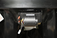
I want to fit the unit so that is fully serviceable from the cockpit side. I'm not sure it will be removable from the engine bay side once the car is built.
First some L shaped ally bars cut and screwed to the front of the unit to create a flange.


Cut the hole in the bulkhead so the heater box will slip in and stop against the flange.
On the engine bay side, bond two 3mm steel strips, drilled and tapped for 6mm screws in the appropriate place for the drilled holes in the heater flange.
Paint it with POR/Hammerite depending on how much money you have left at this point to seal the metal.


On the heater flange, fit some draft excluding type strip so as to make it air tight against the bulk head. This stops fumes from the engine bay and keeps the IVA man happy.


The unit now fits from inside the cockpit.


We now need a hole in the bulkhead somewhere for the heater hose. I have made this at the top of the passenger footwell. As the body is suspended over the chassis on a wheeled frame, I positioned it exactly over the chassis and dropped plumb lines to see where everything will fit. I found that the top chassis rail (in the case of a GENIII chassis) comes to 39cm above the lowest part of the bodywork in this area. That means the hose connection must not be any lower or it will foul the chassis when the body is fitted.
So marking that out, and using a 75mm hose (for that is the size of the flange on the heater) we end up with a hole almost at the top of the bulkhead where it will enter the passenger footwell.

Hole made using a hole saw and the flange fitted from the cockpit side.

I will most likely fit a grill over that to stop it sucking in sweet wrappers or my wife's stockings.

The 75mm hose looks a bit OTT when it is fitted.

Maybe we could fit a reducer and have a smaller diameter hose to run to the footwell. But the heater manufacturer made the unit with that size so I guess we should use it.

We can also see here the satin black surface of the engine bay which looks quite ok when cleaned up.

Pedal box

As supplied by AK. It is a basic metal frame with a shaft running through it which pivots the brake and clutch pedals.
I'll have to 'fess up and say I dropped the box and put a small dent in the side of the box, nothing that would stop it working ok. When fitted to a temporary wooden frame to test and bleed the clutch, the shaft collapsed rendering both clutch and brake pedals useless.
The shaft is fitted to the left side of the box with two tack welds. I believe that these were weakened when I dropped the box and the shaft being only just located in the hole of the box slipped inside so the pedals collapsed.


The fix for me was to strip it all out and have a flange fully welded to the end of the shaft. This will prevent it ever collapsing inside again. I'm going to do this anyway on the next build, or ask AK to do it!

Ideally I would have had a new, slightly longer shaft made but the original one still fits ok as long as we have a small collar on the other side where the retaining nut is fitted. The nut is secured with a spring washer and thread lock.

When testing the clutch pedal, I found it was not quite in line with the push rod for the clutch master cylinder. It operated ok for most of the travel but became tight towards the end of the travel when the pedal was fully depressed. As I had it stripped down I removed 2mm from the width of the clutch arm boss which the shaft sits in. This allowed for some spacer washers to move the clutch arm to the right which then properly lines up with the cylinder push rod.

Next is the throttle pedal. As standard it is just located with a bolt that cannot be tightened as it would seize the pedal. It needs a proper sleeve to rotate around which can be properly bolted in place.
I obtained some 8mm OD tubular steel, cut to length so it protrudes just 1mm from the pedal boss.

We can now assemble it onto the pedal box, properly tighten the nut. The throttle pedal is now more secure and has less lateral play in its movement. However if we tighten too much the pedal will have interference and not move smoothly. The nut needs to back off slightly. It is a nyloc, but even so, best secure it with a lockwire


Now we can assemble the box into the footwell and fit the master cylinders on the engine bay side.

But, before we do that, if you have a cable throttle with a Jenvey throttle body, get the cable fitted now or it will be a very difficult job later on. See here on fitting the cable.


There doesn't seem to be a lot of room to top up the brake fluid!


README_BODY

The rolling chassis is complete to the point where it would be possible to fit the body.
There will probably be some other things to do such as wiring, but for now we turn to the body.

I had this in storage while working on the chassis. It is now in the workshop suspended over the chassis on a wooden frame.

There are at least two items that must be done before fitting to the chassis, heater and pedal box.
But probably we'll also fit lights and possibly cutting out a small section in the passenger footwell, see here

The engine bay I was going to paint body colour. But as supplied there is a nice satin black finish to the smooth surface of the internal panels. As I want a lot of chrome on show in the engine bay, I thought satin black all over would look fine. So I masked of the existing smooth panels, sprayed the rougher surfaces with plastic primer (grey), and then two or three top coats of gloss black. As it is such a rough surface the gloss comes out more satin and looks ok.

I'll do the same with all four wheel arches before the body get fitted.