This is all about a LS3, Omex ECU and cable throttle with Jenvey throttle body. Probably similar for Canems but the software for mapping is will be different I would think.
First the essentials.
Fuel in tank and all fuel line connections tight. Especially check the connection onto the fuel rail.
Check all coolant hoses are tight.
Remove fuel pump relay if you want to spin the engine over with no plugs in.
Coolant. Advised to use OAT (pink/red) coolant. You will need at least 11.5 litres. It comes in ready mix or concentrate.
Oil. The engine has a shallower sump from original so a little oil may need to be drained out.
It came pre-filled with oil so I have left that in place.
By now I have all electrics connected and wired up. I couldn't be arsed to frig up a temporary dashboard, oil gauge and all bits necessary to start the engine way back before I had the body on. So where I am now is all connected as per final setup and ready to go.
Taking the plugs out is a pain, especially with a GEN III chassis. Lord knows how I'm going to get them out to change at first service. Anyway, spinning the engine over doesn't always get the oil pressure going enough to register. I really wanted to know the oil pressure is going to be there so I rigged up an oil gallery priming solution.
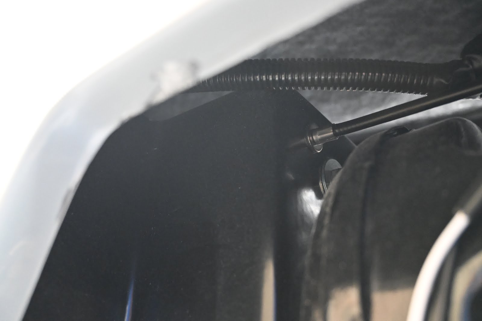
 At the front nearside of the block is an allen key head plug. Remove it and insert a 16mm hose adaptor. Connect to this a drill driven pump (from Ebay, natch). Drain two litres of oil into a clean container, prime the pump, connect up, switch ign on. With drill running at full revs the oil light went out and I saw ~20psi pressure. So this has given confidence the gauge and light sensors are working, and also that we have an engine primed with oil from top to bottom without having to turn the engine over.
The 16mm dia threaded adaptor is at the end of the hose and screwed into the oil gallery at the front nearside of the engine.
Now we need a laptop running Windows (although I didn't check software is available for Linux, but well done if you have Linux anyway) and a piece of software called MAP4000 downloaded from Omex web site. A USB to serial cable is also required unless you have an ancient laptop and have serial ports. There is nothing special about the cable, don't spend loads on a special cable, just a standard USB to RS232 9-pin male is fine.
So, install software, open it and drop down the ECU tab at the top, choose connection setting. If a port doesn't appear you may need to install drivers for USB to RS232. Select the port.
Switch on ign but don't start engine.

On the setup screen are TPS settings. Make a note of the RAW setting on the left of the screen. Click on TPS min value and change it to whatever RAW was plus 2. In my case RAW was 9 so I set TPS min to 11
Now push the throttle pedal to fully open and note the new RAW number. Now set TPS max to RAW plus 2.
That's it. Now press the start button. The throttle may need to be opened a little to get it off a lumpy tick over. It will get hot and smoke and smell like mad. This is normal. But not if it goes on too long.
If it doesn't start then back to basics. Do we have a spark at the plugs, and does it come at the right time? Do we have compression? Do we have fuel entering the cylinders?
Take at least one plug out, lay it against the block to earth it and crank the engine. We should have a blueish spark. It won't be dramatic and hard to see in sunlight.
Stick a compression tester in the plug hole and crank the engine. A finger will do. If you can seal the hole against the pressure, there ain't enough of it.
Finally fuel. Are the plugs wet? At the front of the nearside fuel rail you'll find a shraeder valve. Depress it with a small screwdriver and crank it over and expect some air followed by spurts of fuel. Just like bleeding the radiators at home.
I ran it for about 1 min and then shutdown. Check all fuel, water and oil connections, joints etc. Check under the car for pools of fluid. I was lucky to have no leaks anywhere. Touch each of the exhaust ports to see they are all same temperature, means it was firing on all 8 cylinders.
I now went through the TPS settings again as the RAW figure changed slightly.
There is a small allen screw on the front of the throttle mechanism. It is spring loaded and sets the opening for the butterfly in idle position. Try to feel where it first starts to engage and then screw in another half to one turn. Reset TPS min and max if necessary (these settings are with engine off).
Now run the engine again and bring it to temperature. Check the temp on the screen and on your dash gauge. I found my dash gauge lagged behind the laptop display but got there eventually.
Omex ECU sets the fan to come on at 95 degrees. Check that happens and that air is flowing from outside in. If not reverse the fan connections.
Shut down and check oil, water and again all connections.
The fuel mapping can wait until the engine has run a few thousand miles to loosen up but there is one thing we can do now. At the bottom of the setup screen there are values for the Lambda sensor in the headers. F.B.1 & F.B.2. Ideally we want these as close to zero as possible. Anything above 10 and it will have trouble with passing emissions test, as well as running in a sub optimal fashion.
If it is high (mine was 30 which is the upper level of the possible display) it is running too rich, we need to adjust.
At the top left of the screen is a tab called 'Standard'. Pull down the twiddle at the side and select 'mapping'
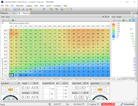
We now have this screen. With the engine running on idle, at the bottom there will be a square highlighted with black edging. If the FB1 & FB2 readings on the first page are high, click on the square where the black edging is and lower the setting. Mine started at 40 and I ended up with 18. But lower it in increments, it doesn't like big jumps.
If the difference between two adjacent squares are then too much, the black edge will hunt around between the two. The engine may also be hunting. So click into the next square and lower that as well. Mine started out at 40, I lowered it to 20. Keep going back to the setup page to check the F.B settings, they will hunt around a bit but should be in the range 8 - 11, or if possible lower.
After this you may want to again adjust the throttle idle opening with the allen screw, and then adjust again the TPS min (leave TPS max as it is).
The thing is that when adjusting one setting, it is often the case that that will in turn require an adjustment elsewhere where before it was ok. It is a matter of tuning the figures to get a nice tickover and a low F.B value.
That should do until it goes in to a proper engine tuning specialist who knows what he's doing after a few thousand miles.
Now would be a good time to check the clutch and transmission. Put something in the cockpit to sit on, put it in gear and check where the clutch bites. Mine was too quick from the floor so it will need some small adjustment. Check all gears select ok, as well as reverse. The lack of grinding noises is good.
I have actually videoed all this, but it is far too boring to put up for show.