Thursday 18 July 2019

Handbrake Mechanism

Updated.
There is not a lot of detail about this in the manual. The main thing to figure out is how to mount the bar so that it is stable but allowed to easily swivel. I think the idea was to basically just have the bar mount on a 8mm bolt and probably secure it with a couple of lock nuts. I prefer to fit some bushes.

First thing is that the angle of the bar did not allow a proper alignment of the pulley wheel to the brake cable.

I increased the bend in the bar by 10mm so the cable had a straight run on to the pulley wheel from the cable mount in the chassis. The aim is to not have the cables being pulled at any angle or it just increases friction which reduces the pull available to engage the brake shoes.
Same with the little swivel bar that connects to the two rear cables that run down to the wheels.
I found it was offset from a centre line of the two cables.

This is easy to fix. I just drilled another hole 12mm to the west of the original hole. It's always to the west. Whenever I have to drill another hole, it's always to the west of the original. Funny that.
Anyway, all these holes, two in the bar and one in the pulley are enlarged to 10mm or 13mm depending on the bush used. Basically we just fit a bush which is a little longer than the width of the bar or the pulley, fit washers/spacers around it, pack with grease and mount in place.
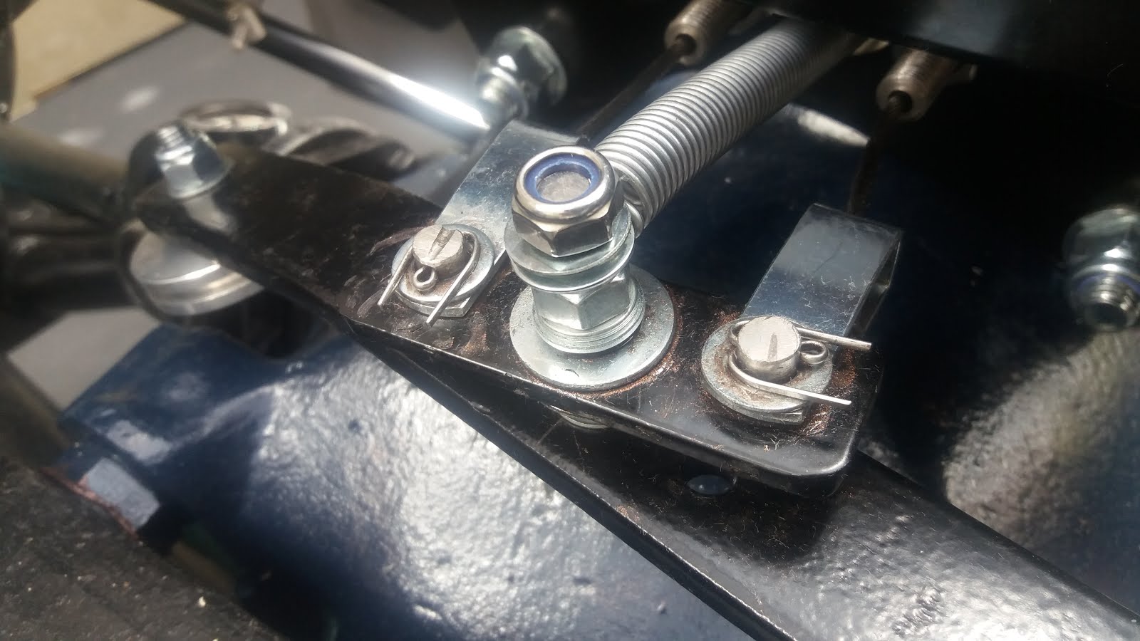
Fo the end pivot and the little swivel plate, I mounted a bolt with washers and a locknut secured with locktight. Fit the bush over it (it is good to not have anything bear onto a threaded bolt, it will just wear and chew itself up in the long run). Now assemble with suitable washers/spacers and finish with a nylock. The result should be sturdy but able to move very freely.

And here it all is:


Here we see the little swivel bar correctly aligned with the rear cables:


So there it is. All fitted, all lined up on lubricated bushes.

The return spring is fitted between the two rear facing cables. A small bracket is made with a slot for one end of the return spring.


I will probably move the fixing point for the spring lower on the upright so as to reduce the angle of incidence on it.


I received the handbrake lever as bits in a bag. Took me a while to understand how it goes together.
After having the parts chromed and plated, here is how it works:


Temporarily fitted to test and set adjustment.


The new cables will stretch a little so I'll leave the handbrake applied for a day or so and then adjust again. We need no more than three clicks for the brake to fully engage. You will need to have the shoes just off engaged when the handbrake is fully off. And put some 3-in-1 down the main cable before fitting. If you do that on the rear cables make sure it is fully drained or it will run down onto the shoes.

Later, with the body fitted, we need to fit the handbrake. There are two locating holes, the one to the rear can be located along with the body retaining bolt. Fit it here and then drill through the forward hole in the handbrake bracket into the chassis, and tap a thread for the bolt.

The handbrake mounting plate fits close to the inernal panel that will be carpeted. If you later buy the interior kit from AK it comes with a leather cover that fits over the handbrake. So, when fitting the internal panel, allow a few mil gap between the plate and the panel for the thickness of the carpet and the leather cover. 

When fitting the cable, drill a hole in the body exactly inline with the slot where the cable will fit into the mechanism. That way the cable has a straight run out into the wheel well. Curve it round the arch of the body and locate it in place with at least two cable ties. If you have the big full fat Jag wheels that came with your Jag donor kit from Simply Performance, you'll find the tyre will rub on the inner wheel arch and foul the handbrake cable. Fit some washers behind the wheel to move it out away from the wheel arch. You won't get enough clearance for the handbrake cable though so after a test fitting, remove it and tidy it away until you get the proper Halibrand wheels, you'll have loads of clearance then.


Friday 5 July 2019

Drive shafts, discs, rear suspension, tie bars

Assembling the drive shafts is just a  matter of following the manual.
Take note about not jamming the joints during assembly.

Push in one end cap all the way until only just past the circlip groove. Any further than strictly necessary to get the circlip in and there will not be sufficient room for the opposite bearing cap.


I'm too tight to buy a hydraulic press so I got me a big 8" vice which does very nicely thank you.

Put extra grease on the needle rollers to make sure they stay in place. Do not fit the grease nipple yet. The grease has to have somewhere to go when the caps are pressed into place.
Keep rotating the joint as the cap is pressed in, feel it for jamming or locking. If that happens stop and remove the cap before it goes too far, it could be some needle rollers are out of place.
Make sure the circlips are properly in place.

When fitting to the diff output flanges, clean off the several layers of POR 15 you have slopped all over the mating surfaces. These need to be an exact fitting. On mine I needed just one spacer ring about 5mm thick, on the other side I needed nothing at all. I got the correct camber by mating the drive shaft right onto the output flange. There is still a need for thin spacers as the mating is actually on a 2mm raised lip that runs around the flange and the drive shaft joint. The resulting gap needed filling with 5 0.5mm shims.

The camber adjust is as per the AK manual. I used the old retaining nuts with the top locking ring sawn off so I could spin them on/off a number of times. Finally I fitted the correct Philidas nuts from SNG Barrett. Ordered a couple of the hub nuts as well. Twenty quid each those things. Special nuts.
Borrowed a heavy duty torque bar from a splendid gentleman called James who is also building one of these things. You need 225 ft/lb turning force on these nuts.
After everything is assembled, check the disc rotor runout.


Runout measured 0.02mm on nearside and 0.05 on the offside. Needs to be less than 0.1mm or 4thou in old money.


All done. Just need to lockwire the caliper bolts and put the wheels on.
Note the calipers are fitted with the bleed screw at the top. When bleeding the system, the bleed nipple needs to be upper most to stop pockets of air forming which are hard to move.

Some torque settings here:
Rear caliper bolts: 54-66 NM
Lower hub carrier pin: 80-100 NM


I ought to mention about the tie bars which seem often to not fit very well.
My nearside had a perfect fit and alignment. The offside was ~4mm short.
The received wisdom is to just drill it out, but I wasn't going to remove 4mm of metal from one place.
So, using a 10mm diameter grind stone, I removed 1mm from the edge of the diff mount tie bar hole, 1mm from the edge of the chassis mount flange, and 1mm from the inside of each of the tie bar holes. In each case it was not about enlarging the entire circumfrence, I just wanted to remove the minimum amount of metal, so in each case it was just about reshaping the hole to be slightly oval by 1 mm. The securing bolts for the tie bars then line up just fine.

Rear suspension arm is fitted as per the manual so nothing to say about it. It fits fine but just looks weird:

That is a fair angle it is sitting at. Sent a pic to Jon at AK and he came back and said "Yup, looks good".

Looking at it, this seems to be a Jaguar diff mount thing. The angle of the swing arm is determined by the relative positions of the front and rear swing arm mounts on the Jag diff mounts.
Tried to find some info about this from Jaguar but failed.
I'm no design engineer but I do declare that as the suspension moves, the effective wheelbase alters.
I bet Mercedes don't build Mr. Hamilton's car like that. Maybe it makes sense on a big XJ40 saloon as it goes over bumps in the road. Anyway, it is what it is. At least the shock unit is angled to operate in a similar plane.


The space between the two ends of the swing arm. The manual says to use the old tube from the recon kit. Later models didn't have that tube. It is required though.
The tube actually fits between one and of the arm and the inside of one of the diff mounts. So it is not the full length of distance between the two arm ends as above.

So, a meter length of steel tube. Two quid from my local hardware and toolshop gaff, will do both sides.
The important thing is the wall diameter. The tube isn't just to cover up the swing arm pin. It is at least partially load bearing when the nut on the pin is torqued up it needs to have a certain amount of crush resistance. So I have a steel tube with internal diameter a little larger than the pin and a wall thickness of 3mm. Cut it to size, it needs to be exact. Measure it, properly.
This size in stainless is a lot of money, so I dipped it in Hammerite/POR 15 ( take your pick) to get the inside coated. When dry, I ran a copper grease soaked piece of rag through to coat the inside of the tube. Coat the pin with copper grease as well and Robert will be your Uncle.

On assembly, just make sure it is all a good fit with nothing loose, including the washer/spacers as you tighten up. And as it is rubber bushes, make sure the arm is in a correct operating position, don't wack the nuts up with it laying on the floor or the poor rubber bushes won't half know about it later on.